Mini project Digital Volt Meter (DVM) using PIC16F877A with C code
DVM Project Overview
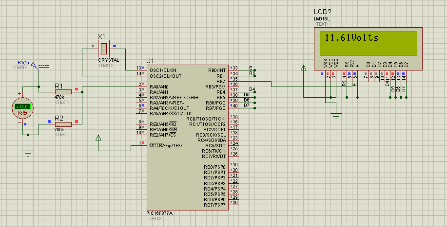
Digital Volt Meter is a Mini Project that I made as my project of the subject ‘Microprocessor Based Instrumentation System’. In this project, I have used three major electronic components. They are PIC16F877A, LCD Display (16 X 2) and Low power Quad op-amp (LM324). PIC16F877A is used as an ADC module which converts the analog input into corresponding 10-bit digital output. It also provides enable and RS signals to the LCD display. LCD Display is used to display the converted digital binary data to decimal format so that user can easily understand the voltage. And finally, Low power quad op-amp is used as a buffer and an inverter. The DVM measures the voltages ranging from –50 V to +50 V
. But PIC can operate only up to +5 V. So to measure the +50 V, the voltage divider is used. This divider divides the input voltage 10 times so that +50V input voltage now becomes +5V at the PIC input. Inside PIC a program is written which multiplies the converted digital value by 10 before sending it to the LCD display. A screen capture of a rough design of the project in Proteus 7.0 Professional is given below.
PIC16F877A ADC Module
The A/D converter module has eight inputs. The conversion of analog input results in a corresponding 10 bit digital output. The A/D module has four registers. They are
- A/D Result High Register (ADRESH)
- A/D Register Low Register (ADRESL)
- A/D Control Register 0 (ADCON0)
- A/D Control Register 1 (ADCON1)
The ADICON0 register controls the operation of the A/D module and the ADICON1 register configures the functions of the port pins.
The structure of ADICON0
| ADCS1 | ADCS0 | CHS2 | CHS1 | CHS0 | GO/DONE’ | – | ADON |
| bits 7-6 : ADCS1:ADCS2 => Conversion channel select |
| bits 5-3: CHS2:CHS0 => Analog channel select [000 = Channel 1, 001 = Channel 2 and so on up to channel 7] |
| bit 2: GO/GONE’ => AD Conversion status bit [1 indicates conversion in progress and 0 indicates conversion not in progress] |
| bit1: Unimplemented |
| bit 0: ADON => A/D on bit [1 indicates converter module is power up and 0 indicates shut down] |
The structure of ADICON1
| ADFM | ADCS2 | – | – | – | PCFG3 | PCFG1 | PCFG0 |
| bit 7 : ADFM => A/D Result format [1 indicates Right Justified and 0 indicates Left Justified] |
| bit 6: ADCS2 => Conversion channel select |
| bits 5-4: Unimplemented |
| bits 3-0: A/D port configuration control bits |
LDC Display (16 x 2)
| Pin No. | Name | Function |
| 1 | Vss | Ground |
| 2 | Vdd | +Ve Supply |
| 3 | Vee | Contrast |
| 4 | RS | Register Select |
| 5 | R/W | Read/Write |
| 6 | E | Enable |
| 7 | D0 | Data bit 0 |
| 8 | D1 | Data bit 1 |
| 9 | D2 | Data bit 2 |
| 10 | D3 | Data bit 3 |
| 11 | D4 | Data bit 4 |
| 12 | D5 | Data bit 5 |
| 13 | D6 | Data bit 6 |
| 14 | D7 | Data bit 7 |
C Source Code
#include <htc.h>
#define data PORTB
#define RS RD0
#define EN RD1

__CONFIG(HS & WDTDIS & PWRTEN & BORDIS & LVPDIS);

float valch0,valch1;

void delay_ms(int n )
{
    TMR1H=0xEC;
 TMR1L=0x77;
 T1CKPS1=0;
 T1CKPS0=0;
 TMR1CS=0;
 TMR1IF=0;
 TMR1ON=1;
    while(n>0)
    {
  while(!TMR1IF);
  TMR1IF=0;
  TMR1H=0xEC;
  TMR1L=0x77;
  n--;
 }
}

float select_adc(unsigned char chnl){    // init_adc(channel name);
    CHS2=CHS1=0;CHS0=chnl;
    delay_ms(10);
    ADON=1;
    ADGO=1;
    while(ADGO);
    return (((ADRESH*256+ADRESL)*5.0/1023)*10);
}


void LCD_Write(unsigned char values,int rs){
 data = values;
 RS = rs;    // rs=0 command and rs=1 data
 EN = 1;
 delay_ms(1);
 EN = 0;
}

void LCD_clear(void){
 LCD_Write(0x01,0);  //this clears LCD
}

void LCD_goto(unsigned char row,unsigned char column){
 if(row==1){
  LCD_Write(0x80+column,0);
 }
 else if(row==2){
  LCD_Write(0xC0+column,0);
 }
}

void LCD_num(int n){

  LCD_Write((n/100)+48,1);
  LCD_Write(((n%100)/10)+48,1);
  LCD_Write((n%10)+48,1);
}

void initLCD(void){

 TRISD=0x00;//as output
 TRISB = 0x00;
 delay_ms(100);


 LCD_Write(0x30, 0); //8 - bit display
 EN=1; EN = 0;
 LCD_Write(0x38,0);    //2 lines mode


 LCD_Write(0x0C,0);    //dispaly on , cursor blinking
 delay_ms(1);

 LCD_clear();LCD_goto(1,0);delay_ms(1);
 LCD_goto(1,7);
 LCD_Write('D',1);delay_ms(100);
 LCD_Write('V',1);delay_ms(100);
 LCD_Write('M',1);delay_ms(100);
 LCD_goto(2,12);
 LCD_Write('v',1);delay_ms(100);
 LCD_goto(2,7);
 LCD_Write('.',1);delay_ms(100);

}

void main(void){
    PCFG3=PCFG2=PCFG1=PCFG0=0;
 ADFM=1;
 ADCS1=1;
 ADCS0=0;
    TRISA=0xFF;
 initLCD();

    while(1){

        valch0=select_adc(0);
        valch1=select_adc(1);


        if(valch0 <= 0.00 && valch1!=0){
            valch0=valch1;
            LCD_goto(2,1);
            LCD_Write('-',1);
            delay_ms(5);
        }

        else{
            LCD_goto(2,1);
            LCD_Write('+',1);
            delay_ms(5);
        }


        LCD_goto(2,4);
        LCD_num(valch0);
        LCD_goto(2,8);
        LCD_num((valch0-(int)valch0)*1000);

    }
}


can u give me a detail pictures due to i cannot see with detail component.hope u can help me.thanks..please email to [email protected]
i have emailed you..see your mailbox…
please send me one detailed picture of the circuit([email protected]). thanking you
can you help me to make a line follower robot using pic 16f877?
[email protected]
can u give me a detail pictures due to i cannot see with detail component.hope u can help me.thanks..please email to [email protected].
can u please give me a detailed circuit of the project. please email me at [email protected]
hi am arun. i have some problem,Error 128 "volt.c" Line 6(1,5): A #DEVICE required before this line
__CONFIG(HS & WDTDIS & PWRTEN & BORDIS & LVPDIS);
how to solve this
i am using ccs c compiler plz help
my mail [email protected]
Hi, can u give me a detail pictures due to i cannot see with detail component.hope u can help me.thanks..
please email to [email protected].
Hi, I too need a detailed picture of the circuit. Please email it to me at [email protected]
can u give me a detail pictures because i cannot see with detail component.hope u can help me.thanks..please email to [email protected]
also send me the pictures please? [email protected]
Is this project will work…….
Because i designed this project not working.
It displaying an block line only..
Kindly give your reply.
THANK YOU
Can you provide me the details of this ?
such as simulation Kindly mail me at
[email protected]
thanks 🙂
Hi, can u give me a detail pictures due to i cannot see with detail component.hope u can help me.thanks..
please email to [email protected]
Hello there.. i cannot clearly identify the other electronic components could you email me the detailed image please? Thank you!
[email protected]
where is the probe in the circuit should I want to measure a component?
could you email me the detailed image please? Thank you!
please email me [email protected]
Hi, kindly email me the schematic with clearer component labels at [email protected]. Thank you
thanks this is good example could u email for the simulation and the source code very grateful for this
[email protected]
i need a clearer schematic diagram of this circuit. If you don't mind sending, please do at [email protected] or [email protected]
thanks
hi good morning great project. can you please email me the picture to see with detail, the components to buy them. i will build it. Thank you very much
[email protected]
can u pls give me a detailed info about the construction of simple digital voltmeter…..
[email protected]
pls give me the picture of detailed component thanks 🙂
my email is [email protected]
can you please provide me with a high resolution pic of the simulation or the .DSN file at this email address ( [email protected])? …thanks in anticipation….. 🙂
hi good morning great project. can you please email me the picture to see with detail, the components to buy them. i will build it. Thank you very much
([email protected])
send me the pictures please? [email protected]
Great project. can you please email me detailed picture of the circuit in isis. i will build it. Thank you very much
([email protected])
pls send me a detailed picture of the circuit
my mail id is
[email protected]..
as soon as possible please
Can you send the picture to see with detail, the components to buy them? There will be very helpful. [email protected]
is there anyway u can convert this to be used for a pic16f917 programmed through ICD 3 using MPLAB
pls email me your complete detail of your project.. [email protected]
Can you send the picture to see with detail, the components to buy them? There will be very helpful. [email protected]
it's not working on my code blocks..
this error is shown ,
fatal error : htd.h : no such file or directory .
Good day sir,
Would be grateful if you could send me the picture to see with detail, the components to buy them.
[email protected]
Hello, It also provides enable and RS signals to the LCD display. LCD Display is used to display the converted digital binary data to decimal format so that user can easily understand the voltage. And finally Low power quad op-amp is used as buffer and as invert er.Great effort in analyzing. Thanks for the post.
HELLO, I NEED THE CIRCUIT DIAGRAM OF THIS CODE.PLEASE GIVE ME CIRCUIT DIAGRAM ON MY MAIL…….([email protected])
pls send me my [email protected]]
What's the output if this.
This is full program
Send me the diagram to my mail [email protected]
sir can u plz send the proteus schematic picture